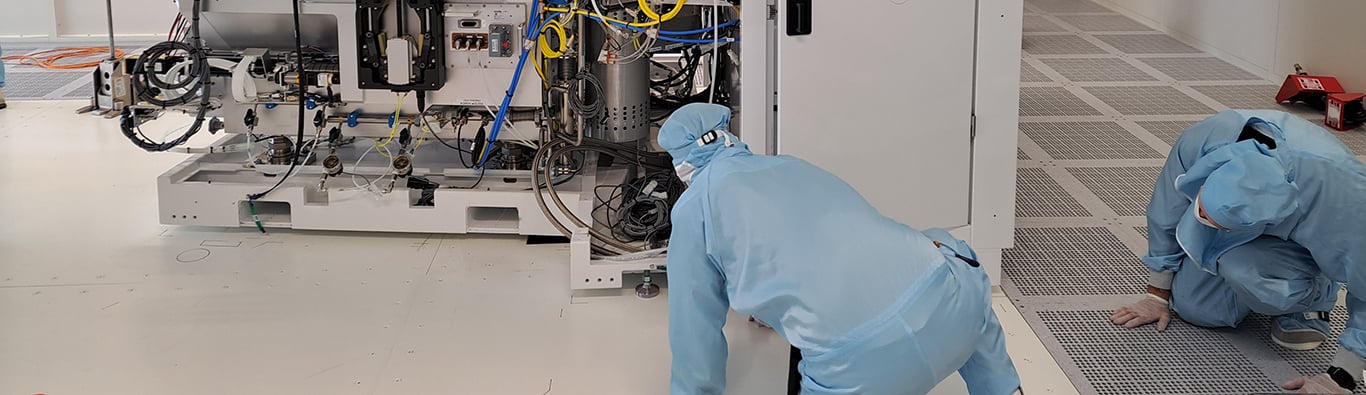
Using a well-made structural machine base versus a substandard base can be a matter of life or death for precision tools like lithography, metrology and ion implanter equipment.
That’s because delicate semiconductor production equipment is especially susceptible to vibrations induced by other equipment, cleanroom plants and unstable foundations.
Structural machine bases are foundational support structures that provide the levels of stability that heavy and vibration-sensitive equipment (typically lithographic, metrology and ion implanter) require.
For the purposes of this article, there are three types of machine bases:
1. Antivibration bases: These essentially are a tabletop floating on active vibration actuators, isolating the table from the fab floor slab.
2. Structural bases: These are used when a tool is too heavy to sit on the Raised Access Floor (RAF) but also does not have a high level of vibration sensitivity.
3. Structural dynamically rigid bases: These are designed not to induce unwanted vibrations. They can be used when the fab slab floor has vibration characteristics equal to or better than the tool to be supported.
IES provide welded steel constructed bases suitable for the second and third types of use cases outlined above.
In this article, we’ll run through the seven key steps of designing and installing the right base and the key considerations for each step.
But first, let’s clarify the difference between a base, a pedestal and a floor.
What’s the Difference Between a Base, Pedestal and Floor?
Structural machine bases are also referred to as “pedestals”, “plinths”, “tables”, “floors”, “pedestal bases”, or simply “bases”. It really depends on which engineer, technician or region you ask.
But, while these terminologies are related, they’re not quite as interchangeable as people might think. Here are the key differences:
- Base: This is the entire assembly that supports the tool. It includes the welded steel structure, complete with a top plate, which is typically bonded to the fab slab.
- Cleanroom Floor: Cleanrooms typically have raised access floors (RAF) to allow for sub floor facilities connections and particulate control. The RAF supports pedestrian traffic and lighter or non-vibration-sensitive tools.
- Pedestals: These are the support columns for the RAF. They’re usually adjustable in height, and are set out in a grid with tie rods to adjacent pedestals.
- Floor Tiles: These infill the grid of pedestals to create the cleanroom floor.
How to Design, Install and Manufacture the Base
Bases are tailored to each specific tool and its unique set of requirements. One size does not fit all.
The base must support the tool load and have suitable vibration performance when the tool is in operation. The design, manufacture and installation can be broken down into seven key steps.
1. Information Gathering
Start by reviewing the installation manual for the specific tool early on in the process. Here’s where you’ll find essential information on the tool, including:
- Tool footprint: This will define the dimension of the base and whether you’ll need to make any cutouts in the top plate to allow access to subfloor facilities. Keep in mind that the entire tool might not necessarily be located on the pedestal. For example, wafer handling modules may sit on the RAF and be isolated from the module to avoid induced vibration. It’s important that bases are not oversized or extend beyond the tool—otherwise, there’s a risk of footfall-induced vibration.
- Tool configuration: Complex tools are often available with multiple configuration options. It’s essential to know at the outset the exact configuration ordered.
- Weights, foot loadings and Centre of Gravity (CoG): This information is required for both the structural design of the base but also the vibration modelling we refer to in step four.
2. Site Surveys
When surveying the exact location to install the base, you’ll need to cover the following:
-
Dimensional: Start by completing a 360 LiDAR (Light Detection and Ranging) laser scan under the RAF where the base is to be installed. Then, map out existing facilities running through the area and suitable positions for the base support legs. Finally, produce a suitable design to negate or minimise any sub-floor changes to allow the base to be installed.
-
Vibration: For a structural, dynamically rigid base to perform correctly, you’ll need to secure it to a slab with at least as good vibration performance. Then, position vibration sensors in multiple locations to measure the existing slab vibration signature and to confirm it’s suitable for the tool. You can also measure EM (Electromagnetic) Field and sound pressure levels at this time.
-
Access: Lastly, be sure to consider the route into the cleanroom. That’s because, if the base is dimensionally large, you may need to design it in more than one piece to allow for ingress. You also need to factor in space for lifting equipment (i.e. Gantry A Frame) within the cleanroom.
3. Design
During design, consult a structural engineer to produce a 3D CAD design. Be sure to factor in the following considerations:
- Tool dimensions and facilities cut-out requirements
- Weight of the tool and specific foot loadings (where space under the floor permits, base support legs and slab bonding points are positioned directly under the tool feet)
- It may be necessary to bridge existing services or openings under the RAF
- Dynamically rigid bases will have a significant amount of cross-bracing to stiffen them to improve vibration performance
4. Maintenance and Monitoring Finite Element Modelling (FEM)
Next, work with a vibration expert to run your 3D CAD design through a FEM process. This models how the designed base will behave with the tool installed.
If the design does not meet the OEM’s tool vibration specification, then you’ll need to collaborate closely with the designer to make changes to the base design to improve its stiffness.
Typically, changes might include a combination of increased bracing, sectional thicknesses of the construction materials or additional fixing points to the slab. Repeat this process until the design produces acceptable results from the FEM.

5. Manufacture
Ensure you use suitable materials and processes when manufacturing the base.
For example, IES bases are fabricated from box section steel with a detachable 10mm steel top plate. Typically these are powder coated, but can be in stainless steel.
Our manufacturing process is also approved to Class 2, and all steel bases are CE-marked.
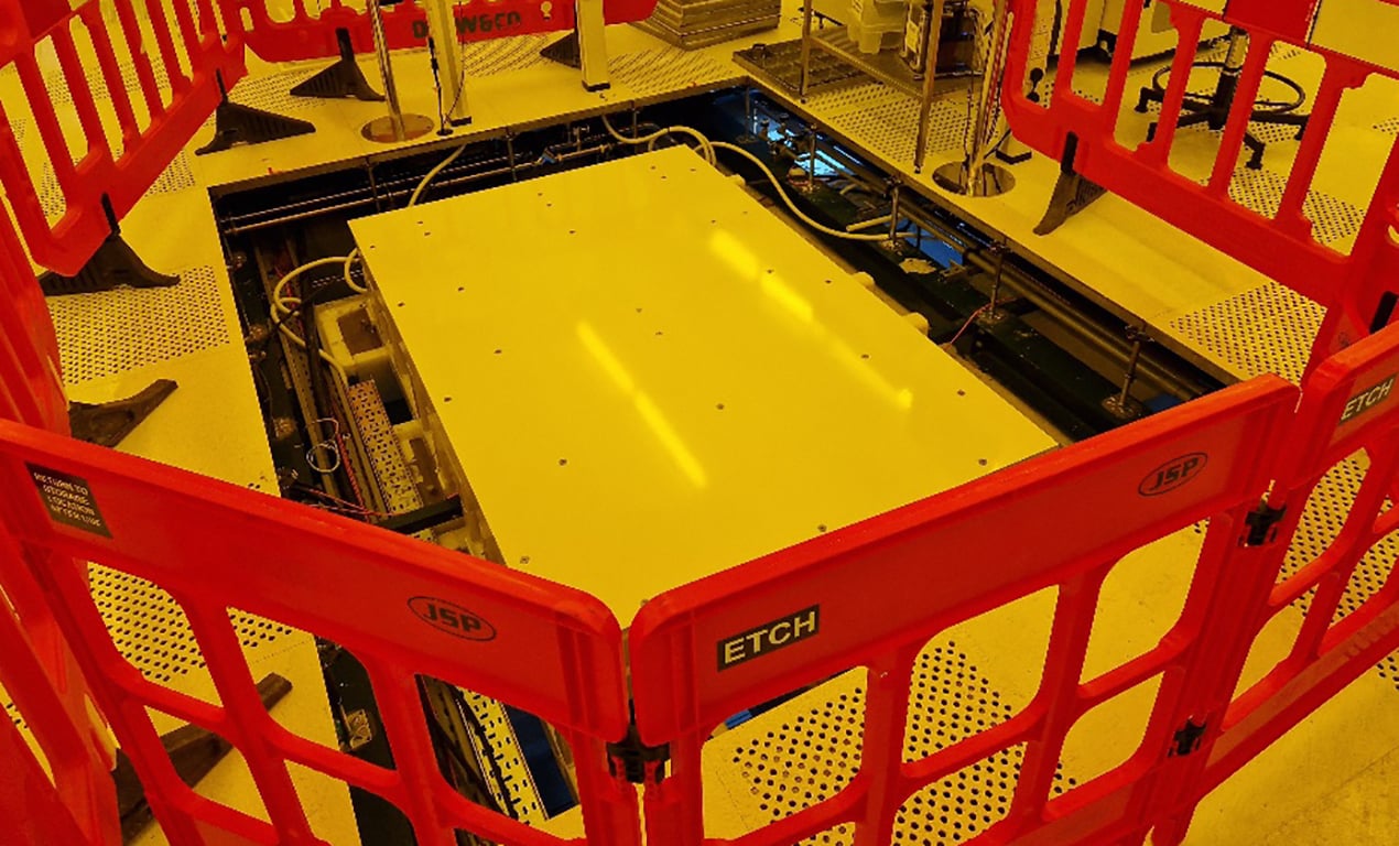
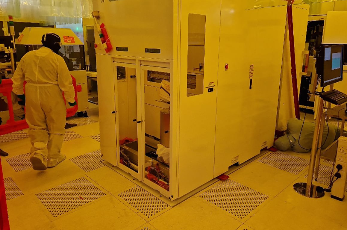
6. Installation
Ahead of the installation, you’ll need to remove the RAF and supporting pedestals in the designated location.
Then, carefully lower the base into position, avoiding conflict with any existing services. We typically use an A-Frame to achieve this.
Align the base and adjust the height with levelling screws in the foot positions to match the RAF height. Then, grout all support feet in situ.
Optionally, you might want to use tile edge supports to provide a support structure (isolated from the base top plate) around the periphery of the base. This will support any cut floor tiles.
7. Post Installation Vibration Checks
Once the tool is on the base and fully operational, you’ll need to conduct a post-installation vibration survey.
This demonstrates that the base is performing correctly and within the tool’s vibration specification. It’s also an essential document for you to keep in case of any issues with the tool’s operation.
Looking for Expert Structural Machine Base Design and Installation?
We’ve been designing and installing structural machine bases for delicate semiconductor production tools since 1991.
Our experienced engineers can handle your entire project from start to finish, from initial assessment, design and build to installation, testing and commissioning.